Freshman Rider
 
Currently Offline
Posts: 85
Likes: 3
Joined: May 24, 2013 22:49:43 GMT -5
|
Post by dakotafig on Feb 15, 2014 1:18:17 GMT -5
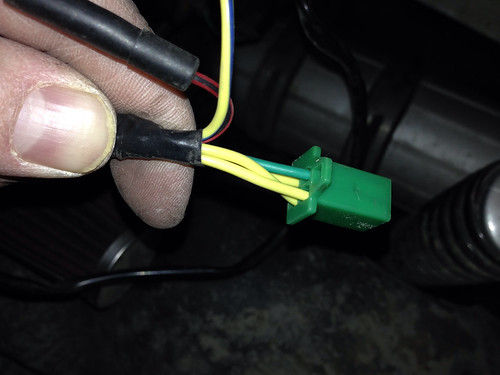
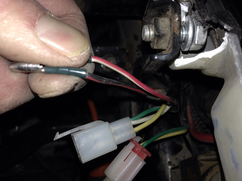
Actually, I guess I still have the questions about the pickup in the stator bundle. There are two wires from the stator and two wires on the scoot (the individual connectors) and I don't know which color goes with which. 4th and 6th pictures from first post...... Can anyone answer this? |
|
Freshman Rider
 
Currently Offline
Posts: 85
Likes: 3
Joined: May 24, 2013 22:49:43 GMT -5
|
Post by dakotafig on Feb 14, 2014 22:22:14 GMT -5
Ok, that makes sense then. So, if I want to run a relay off the white wire for the headlights I probably need a 12vac relay and not a 12vdc relay.
|
|
Freshman Rider
 
Currently Offline
Posts: 85
Likes: 3
Joined: May 24, 2013 22:49:43 GMT -5
|
Post by dakotafig on Feb 14, 2014 19:07:49 GMT -5
After I posted that it dawned on me that doesn't make any sense, the fuel enricher is DC because that's how you test it is putting 12vdc to it...... Unless I'm missing something.
|
|
Freshman Rider
 
Currently Offline
Posts: 85
Likes: 3
Joined: May 24, 2013 22:49:43 GMT -5
|
Post by dakotafig on Feb 14, 2014 18:59:00 GMT -5
So the white wire is a frequency output, so it's AC? The fuel enricher actually runs off AC? What voltage is it?
|
|
Freshman Rider
 
Currently Offline
Posts: 85
Likes: 3
Joined: May 24, 2013 22:49:43 GMT -5
|
Post by dakotafig on Feb 14, 2014 17:11:30 GMT -5
Actually, I guess I still have the questions about the pickup in the stator bundle. There are two wires from the stator and two wires on the scoot (the individual connectors) and I don't know which color goes with which.
4th and 6th pictures from first post......
|
|
Freshman Rider
 
Currently Offline
Posts: 85
Likes: 3
Joined: May 24, 2013 22:49:43 GMT -5
|
Post by dakotafig on Feb 14, 2014 17:07:05 GMT -5
alleyoop, that document is great. I have seen the diagrams individually, but not all in one place. That should get me going. I was planning on actually putting two relays in, one for the ignition to take the "ignition on" load away from the switch and one for "engine on" load.
|
|
Freshman Rider
 
Currently Offline
Posts: 85
Likes: 3
Joined: May 24, 2013 22:49:43 GMT -5
|
Post by dakotafig on Feb 14, 2014 15:08:52 GMT -5
Ah, good idea on both of those. Maybe a good idea to put those ideas up for new members in the forum information section.
|
|
Freshman Rider
 
Currently Offline
Posts: 85
Likes: 3
Joined: May 24, 2013 22:49:43 GMT -5
|
Post by dakotafig on Feb 14, 2014 12:22:42 GMT -5
It would be nice if you made a "test board" that users could use to test things like image attachment, links ect and that would eliminate the learning curve in the normal boards. For example, I just posted a bunch of stator pictures and I had to edit that post several times until I figured out exactly how I needed the BBC code from Flickr to make it work correctly. Just a thought.....  |
|
Freshman Rider
 
Currently Offline
Posts: 85
Likes: 3
Joined: May 24, 2013 22:49:43 GMT -5
|
Post by dakotafig on Feb 14, 2014 11:00:31 GMT -5
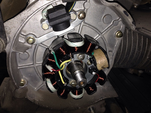
Ok, so my status so far, and the eventual goal of this post is to have a good in depth guide to upgrading from an 8 pole to an 11 pole stator. A little bit of background, from what I have read I am fairly lucky because I have stock 55 watt headlights, and they are very bright. I never had a problem driving at night. One day I noticed my headlights didn't come on anymore. All my dash lights, turn signals ect worked. Also at the same time, suddenly my battery would be dead after about 2 days of driving. Sooo...... The 55 watt headlights and the rest of the load was probably to much for the stock rectifier and it died. I purchased an 8 pole stator and matching rectifier from John (tvnacman). Pulling the stock stator was easy after taking the air shroud and cooling fan off. I used a gy6 flywheel puller to remove the flywheel. After writing this I have realized my flickr account is being a pain and not embedding pictures...... I will get that figured out and continue this post...... New stator installed:  Now the real questions. The new stator has these outputs (three yellows, green, red/black tracer, yellow/blue tracer):  Here is what the stock stator plugged into on the scooter (yellow, white, green):  Here is the wires going to the stock CDI (red/white tracer, black/red tracer):  Here is the wires on the new rectifier (red, green, black, white):  Lastly, here is the stock rectifier with the plug going to it (yellow, white, red, green):  This much I know.... The three yellow wires from the stator need to go directly to the three yellow inputs on the new rectifier. For those I just plan on running three new wires all the way up. The green wire from the rectifier should go to the scooter ground, which I believe should be the green from the stock rectifier plug. The red wire should go to the main DC power distribution of the scooter, which should be the red in the stock rectifier bundle. Is this correct so far? Also, for the cdi wires coming from the new stator, which color goes to which one for the actual scoot cdi connection? What do I need to do with the rest of the wires coming from the regulator? I'm working on a wiring diagram piece by piece and I will be posting that soon. Basically, for the new rectifier, what is the function of each of those wires, the red, green, black and white? Thanks, Eric. |
|
Freshman Rider
 
Currently Offline
Posts: 85
Likes: 3
Joined: May 24, 2013 22:49:43 GMT -5
|
Post by dakotafig on Feb 14, 2014 0:02:24 GMT -5
Have you checked the function of your stator and rectifier? That is where I would start.
|
|
Freshman Rider
 
Currently Offline
Posts: 85
Likes: 3
Joined: May 24, 2013 22:49:43 GMT -5
|
Post by dakotafig on Feb 12, 2014 14:35:35 GMT -5
I figured it out. (spent way to much time looking.....) ProfiCAD. If anyone has any starting source drawings they would like to share that would be great. I have seen several that I will use as starting points, but if I don't have to reinvent....  I basically want to put a bit more detail in to things I have seen online and publish in a high definition. The drawing I have seen by Rebel was great, just the hosted image quality wasn't the greatest. |
|
Freshman Rider
 
Currently Offline
Posts: 85
Likes: 3
Joined: May 24, 2013 22:49:43 GMT -5
|
Post by dakotafig on Feb 12, 2014 12:24:13 GMT -5
In my opinion a problem like that is most likely fuel related. Electrical issues are typically on or off. In other words electrical components either work or they don't (maybe intermittently sometimes). This isn't always the case I understand, but more often than not......
|
|
Freshman Rider
 
Currently Offline
Posts: 85
Likes: 3
Joined: May 24, 2013 22:49:43 GMT -5
|
Post by dakotafig on Feb 12, 2014 12:16:33 GMT -5
Does anyone have any recommendation on software to create a wiring diagram that looks like this: diagram? I have tried just about everything on this page: wiring diagram software and the closest was probably Smart Draw, but it still had lots of limitations. I'm not necessarily looking for free, I just want quality. I have found lots of scooter wiring diagrams online and I'm just not satisfied with them. The best I have seen so far was probably by a user named Rebel on another board. If you have any input please let me know. |
|
Freshman Rider
 
Currently Offline
Posts: 85
Likes: 3
Joined: May 24, 2013 22:49:43 GMT -5
|
Post by dakotafig on Feb 5, 2014 23:07:56 GMT -5
Well, I'm not do much looking for an absolute oil pressure, but really more of a proof of pressure. I'm even thinking a pressure switch.
For the few that have an oil cooler connection, where would that be at?
|
|
Freshman Rider
 
Currently Offline
Posts: 85
Likes: 3
Joined: May 24, 2013 22:49:43 GMT -5
|
Post by dakotafig on Feb 5, 2014 0:44:14 GMT -5
I second the flat piece of steel with a gasket or rtv, as long as you let it cure. And if it was me, I would only use red rtv......
Why rinky around with something that if it fails could crater your engine.
|
|

