Freshman Rider
 
Currently Offline
Posts: 85
Likes: 3
Joined: May 24, 2013 22:49:43 GMT -5
|
Post by dakotafig on Feb 22, 2014 15:55:05 GMT -5
no offense but whats the point of putting more complicated efi onto an already simple carbed scooter Better throttle response, much better performance, easier to start the engine, easier "tuning of jets"... Carbs have two advantages. Cheaper and don't need power to run. However, in my mind the power issue is negated by the fact my carb is finicky enough it would NEVER start with the kick starter. Wilds hit it on the head, EFI is better in every respect except for cost, and when I need mine (for as close as your going to get a Chinese scoot) to be a workhorse the cost becomes less of an issue. |
|
Freshman Rider
 
Currently Offline
Posts: 85
Likes: 3
Joined: May 24, 2013 22:49:43 GMT -5
|
Post by dakotafig on Feb 21, 2014 0:44:10 GMT -5
I am really interested in seeing how yours turns out. I just did a lot of re-wiring on mine mostly because of an 11 pole stator upgrade, but also to have the future capability of FI.
The thing I have seen that is kind of vague is the throttle cable modification to make it hook up to the throttle body. Did you have to do much with that?
|
|
Freshman Rider
 
Currently Offline
Posts: 85
Likes: 3
Joined: May 24, 2013 22:49:43 GMT -5
|
Post by dakotafig on Feb 21, 2014 0:39:45 GMT -5
If you ever have to get into the cvt, my opinion is to always check the clutch pads and rollers. Your that far so might as well, never know what you might find. I got a really bad vibration once, even had a rattle sound to it but it was still driving. Finally took clutch bell off and one pad had completely broken apart and spit pieces everywhere. My point here being that happened without a belt breaking or really riding hard ect. With the original Chinese parts it never hurts to look things over in the cvt, especially if you have a belt breaking event.  |
|
Freshman Rider
 
Currently Offline
Posts: 85
Likes: 3
Joined: May 24, 2013 22:49:43 GMT -5
|
Post by dakotafig on Feb 19, 2014 23:47:07 GMT -5
You should be able to take the sender out and check the resistance versus float angle. If the resistance doesn't change as you move the float or if the float circuit has zero resistance or is open then the sender is bad.
I believe this is fairly common.
If the resistance looks ok you would want to look up what the resistance range should be and verify. If the sender looks good than it is wiring or your gauge.
|
|
Freshman Rider
 
Currently Offline
Posts: 85
Likes: 3
Joined: May 24, 2013 22:49:43 GMT -5
|
Post by dakotafig on Feb 19, 2014 10:54:15 GMT -5
3000 miles really isn't anything. How long have you been running on it with a broken speedo? There was a thread a while back about the miles people got on scoots, and if memory serves me correctly you should be able to get 10 - 15k on them if you take care of them. In other words check valves regularly, change oil, run at correct rpms ect......
I might be off a bit on mileage, but my 2 cents is take care of the gy6, and it will do ok.
|
|
Freshman Rider
 
Currently Offline
Posts: 85
Likes: 3
Joined: May 24, 2013 22:49:43 GMT -5
|
Post by dakotafig on Feb 18, 2014 18:12:10 GMT -5
It really wasn't that bad. If I was just going to upgrade the stator and rectifier, probably a 4 with 10 being the hardest. But, that doesn't give the wiring any protection at all. Obviously doing something the second time is much easier than the first so I could do the complete wiring change over in an evening this second time around. I would say my mods were probably only a 5 in terms of difficulty just for the fact I had to fish wires through the body, ect. I guess not really that hard, just takes some time.
That's why I'm hoping I can get some complete instructions and diagrams posted soon so maybe I could take the learning curve out for somebody.
|
|
Freshman Rider
 
Currently Offline
Posts: 85
Likes: 3
Joined: May 24, 2013 22:49:43 GMT -5
|
Post by dakotafig on Feb 18, 2014 12:19:38 GMT -5
Turbo, ha, my wife is tired of the stator project on the scoot. Don't think a project like that would go over well.  She wants me to ride it as much as I want to ride it because my truck uses a lot more gas than this does. On a side note, holy cow what a difference this upgrade made. My lights are MUCH, MUCH brighter and I didn't even think they were that bad to begin with. I also feel better about the way it is wired now. Basically my headlights, tail lights and dash lights could all short out and they would just blow their own fuse and I could still start it. I'm hoping to post a wiring diagram of what I did sometime this week. |
|
Freshman Rider
 
Currently Offline
Posts: 85
Likes: 3
Joined: May 24, 2013 22:49:43 GMT -5
|
Post by dakotafig on Feb 17, 2014 11:43:04 GMT -5
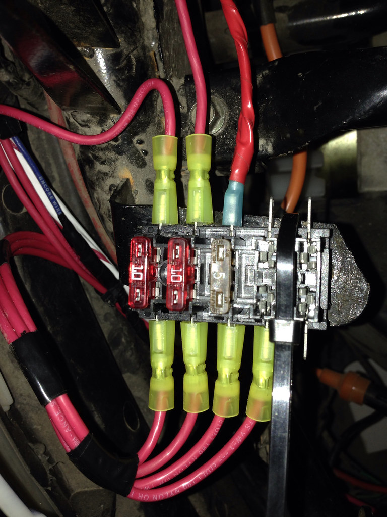
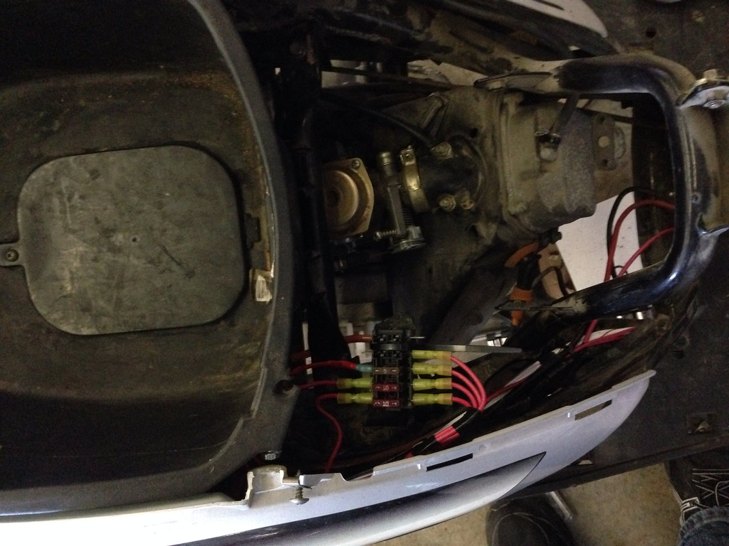
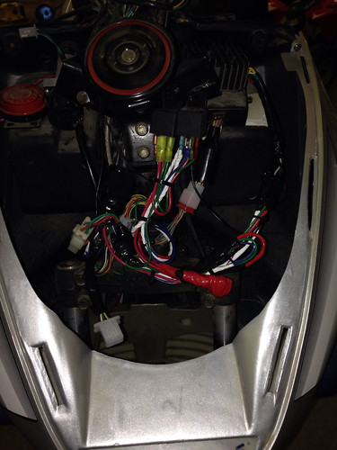
Well, I have learned a lot and found a couple of potential other issues over the weekend. The first issue was the ignition switch not shutting off the scoot. Well, I took the switch out and found the green wire was broken off at the solder joint. I have been having an issue with it cutting out at various times while driving it and I'm not for sure if this could have anything to do with it or not..... Anyway, so I soldered the wire back on and all is well on that front.  The biggest thing was the fuse block. I went to O'Reilly's and purchased a 5 circuit fuse block. Here is my thoughts with that: Circuit 1: Headlights Circuit 2: Rectifier output Circuit 3: Ignition switch Circuit 4: Dash lights etc. Circuit 5: Future (fuel injection  ) Since I have a uni filter I don't have the stock air box, so I used one of the stock air box bracket and bent it flat to use as a mounting spot for the fuse block. I ran a main wire from the battery with a 20 amp fuse to supply power to each circuit on the fuse block. Then, each one of the individual power feeds runs up to the front. If I would have thought that through in the first place I could have bundled the wires and pulled them up at one time, but I ended up pulling three separate wires at three separate times. The ignition switch feed uses the existing stock wire, but the only thing it powers is the power to the ignition switch. I cut the other red wire that used to go to the stock rectifier. I'm not finished with the last circuit in these pictures yet, and I still have a zip tie holding the fuse block down, but I will screw that down tonight.    Up front, I used two relays for the headlights. They basically follow the exact wiring diagram photo I posted earlier. You can see them just below and to the right of the horn.  Some of you might ask why did I put the rectifier directly to the fuse block on its own wire. Well, as I took one of my mirrors off I found one of the running light wires had chafed through and actually shorted out. Well, being the fact there was no fuse between the rectifier and anything else that could have very likely contributed to the death of the factory rectifier. So, with its very own fuse almost directly to the battery, it would never be affected by any other short circuit or other wiring malfunction. I will probably end up increasing the fuse size to a 15 amp because if the 11 pole stator/rectifier is 135 watt, that is a little over 11 amps. My thoughts on fuses are always start small and go from there....... Hopefully tonight I can get everything completely buttoned up. The snow is almost completely melted so I could be riding.  I do have one minor question, I haven't hooked up the fuel enricher yet and I will have to poke a new wire into the little two wire plug. Does anybody have any recommendations on getting the wires out of the plug without destroying it? |
|
Freshman Rider
 
Currently Offline
Posts: 85
Likes: 3
Joined: May 24, 2013 22:49:43 GMT -5
|
Post by dakotafig on Feb 16, 2014 21:50:17 GMT -5
What is the max wattage output of the 7 wire rectifier? Or max current output?
|
|
Freshman Rider
 
Currently Offline
Posts: 85
Likes: 3
Joined: May 24, 2013 22:49:43 GMT -5
|
Post by dakotafig on Feb 16, 2014 17:00:11 GMT -5
Quick update on the not shutting off thing, completely unrelated to the stator upgrade. I would ground out the wire and it shut off. Next step was checking connections ect. Well, I found that if I wiggled the wires going into the back of the switch it would trigger the kill wire. So, I guess I'll be opening that up to see what is going on in there.
Also, I checked the voltage at the battery, 14.3 volts at any speed. Awesome......
I have lots of pictures of the fuse block and wiring I did and I will be posting those later.
Thanks for everyone's help!
|
|
Freshman Rider
 
Currently Offline
Posts: 85
Likes: 3
Joined: May 24, 2013 22:49:43 GMT -5
|
Post by dakotafig on Feb 16, 2014 11:41:02 GMT -5
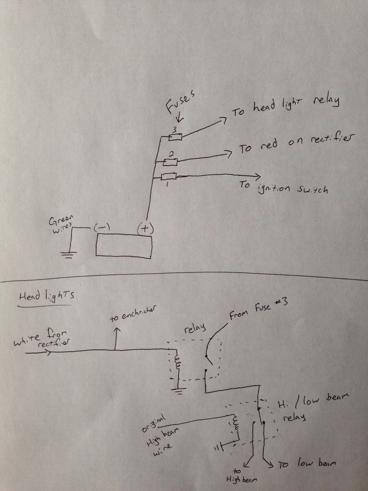
Pictures tend to tell a lot more than trying to explain it. So here is a quick sketch of how I am wiring the headlights and stator power.  |
|
Freshman Rider
 
Currently Offline
Posts: 85
Likes: 3
Joined: May 24, 2013 22:49:43 GMT -5
|
Post by dakotafig on Feb 16, 2014 10:42:45 GMT -5
Ok, I have verified when the ignition switched is turned off the voltage is turned off on the black wire. I will check the grounding and see what I have going on there, I just didn't know exactly how the kill was activated on the CDI.
I didn't have my dmm in the shop last night so I will check that out this afternoon.
As for the headlight relay you are right, I can use a single pole double throw relay. Low beam power can go through the NC contact and the high beam power can go through the NO contact. Then the original high beam power can run the coil of that relay. I would have probably figured that out, it was just to late last night for me be thinking straight.
|
|
Freshman Rider
 
Currently Offline
Posts: 85
Likes: 3
Joined: May 24, 2013 22:49:43 GMT -5
|
Post by dakotafig on Feb 16, 2014 0:56:18 GMT -5
Well, the scoot lives again, sort of....... I got everything back together and it started right up, and I would even swear to it that it started up easier and seemed to run a bit smoother. I'm sure if there is a higher voltage to the primary on the coil then it could have a better spark.....
Ok, well the issue is now it is not shutting off when I turn the key off. I can still kill it with the red kill slider switch, but it isn't shutting off with the key switch. The black/white stripe wire comes out of the key switch and turns into a grey/white stripe wire after the connector. At the cdi the kill wire is indeed black/white stripe. I verified there is no voltage on the black wire when the ignition is shut off. So, how exactly does the kill wire function?
On a side note, I'm am absolutely astounded the headlights and all the rest of the lights for that matter were ran with basically an 18 gauge feed wire. One 55 watt headlight is 4.6 amps at 12 volts! I'm sure the rest of the bulbs are not insignificant on top of that either. I'm actually very happy with my headlights (I've read a lot of them come with some 35 watt version and is the reason for the HID upgrade), so I decided I'm going to put a high beam and low beam relay up front and let them run the headlights. That will eliminate that load from the 18 gauge wiring circuit. I have the white wire running a relay that comes on when the engine is running. I will run a separate power through that that goes to two more relays. I am going to use the high and low beam wire to run the coil of the second two relays. So, it will take a total of three relays but I will feel a lot better about feeding the light bulbs independent of the small yellow wires.
|
|
Freshman Rider
 
Currently Offline
Posts: 85
Likes: 3
Joined: May 24, 2013 22:49:43 GMT -5
|
Post by dakotafig on Feb 15, 2014 15:43:54 GMT -5
I have a 150 gy6.
Thanks for the pictures. I looked at the stator a little closer and then it became fairly obvious to me which was the pick up wire. Sometimes I ask stupid questions even though I have the answer right in front of me.
|
|
Freshman Rider
 
Currently Offline
Posts: 85
Likes: 3
Joined: May 24, 2013 22:49:43 GMT -5
|
Post by dakotafig on Feb 15, 2014 9:56:52 GMT -5
Sorry john, somehow I missed your initial reply. I will trace/meter the wires back on the scoot side and see which is which so I can hook them up correctly to the pickup.
Thanks for your help.
|
|
