|
|
New forum
by: JR - Jun 27, 2013 9:20:37 GMT -5
Post by JR on Jun 27, 2013 9:20:37 GMT -5
Took care of.
JR
|
|
|
|
New forum
by: JR - Jun 27, 2013 6:44:04 GMT -5
Post by JR on Jun 27, 2013 6:44:04 GMT -5
Can someone here clue me in as what is going on?  JR |
|
|
|
Post by JR on Jun 27, 2013 6:35:28 GMT -5
Justguy1 I'm going to ask this again and lets move on from the battery disconnect switch, we're beating a dead horse here and it's apparent that you have a live scooter as far as voltage goes when the switch is in the on position. Again if you're not sure then to test this scooter eliminate the switch and put the original negative battery cable back on the negative post of the battery. Now I want you to go back to the key switch plug, the one you posted in the picture. Unplug the key switch. Then take the plugin that goes back toward the engine/fuse box and put a jumper wire in the plug from the red wire to the black wire and see if; your scooter engine will turn over or start. if your horn, blinkers etc will work. Get back to me when you do this. Also note: I said this once before and I'll say it again as an electrician you NEVER break or put a disconnect switch of any kind on the NEGATIVE side of the circuit. When we get this scooter straightened out if you still want to use the battery disconnect then we'll do it right.  JR |
|
|
|
Post by JR on Jun 27, 2013 6:26:47 GMT -5
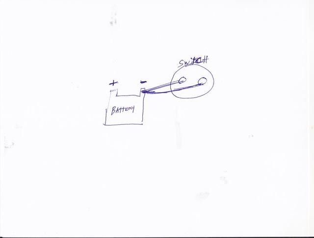
Well from what he said and wrote in the picture he put up THIS IS HOW HE WIRED IT. But he hasn't answered. I am just trying to help so he can wire up the switch correctly. Alleyoop  No Alley if he did what he said here than again it is wired right. Think about it? If you remove the negative battery cable from the battery and trace it out it will go to the frame where it is "grounded". If you then put that wire on a switch and then run another wire from the switch to the same negative battery terminal where you removed the first wire from then if the switch is in the "on" position it is grounded, simple as that. Now this is based upon his description above. |
|
|
|
Post by JR on Jun 27, 2013 6:21:41 GMT -5
If there was NO switch.. let's take the switch out of the equation.. and take the BOTTOM wire and we connect it back to the Negative terminal where it was.... Then what wire is grounded to the frame??
Yes, when you removed the wire from the negative battery post it was grounded to the frame to begin with. Then if you put it on the switch and ran another wire from the switch to the same negative battery terminal that you removed the wire from it would be wired correctly, it doesn't matter what color the wire is although negative is generally black or green.
You also said that if you turn this switch off then the scooter has no power it is dead and this tells me it is wired correctly so I'm not trying to sound rude here it's time to move on from the battery disconnect switch and lets see what we can do to figure out what is damaged/wrong.
|
|
|
|
Post by JR on Jun 27, 2013 0:11:08 GMT -5
ALL DID was take the wire that was connected to the battery on the negative side and put that on the bottom of the DISCONNECT then ran another wire back to the same terminal I took the OTHER wire off of
If he did this then it is correct. The wire he removed from the negative battery post was already run to the frame thus it is grounded to the frame or the scooter wouldn't start etc.
Then he ran another wire back to the terminal he took the cable off of which would complete the ground circuit with the switch on. The way he worded it is confusing and he verifies that with the switch off he has no power at all.
JR
|
|
|
|
Post by JR on Jun 26, 2013 23:26:10 GMT -5
Justguy1 You have the switch wired correctly so now lets do this. I want you to unplug the key switch, the plug in the picture.
Now on the plug end that goes to things in your scooter, not the plug end that goes to the key switch I want you to put a wire jumper from the red wire to the black wire and see if things will work on your scooter, blinkers, horn, etc. and see if it will start.
JR
|
|
|
|
Post by JR on Jun 26, 2013 23:22:32 GMT -5
Only in rare circumstances does one put a battery disconnect on the negative cable side. After all even the starter solenoid relay is just a electromagnetic switch and it is on the positive side. Even on AC current like in your home the light switches are on the positive side.
At this point it doesn't matter if he has a battery disconnect switch he just needs to have it hooked up the way it came so we can see what is truly messed up. I've never understood this battery disconnect any way? I've got a 250 with a clock and alarm system, I don't have a weak or low battery issue? Why should one have this problem with a CfMoto? Aren't they better? ;D
JR
|
|
|
|
Post by JR on Jun 26, 2013 22:01:21 GMT -5
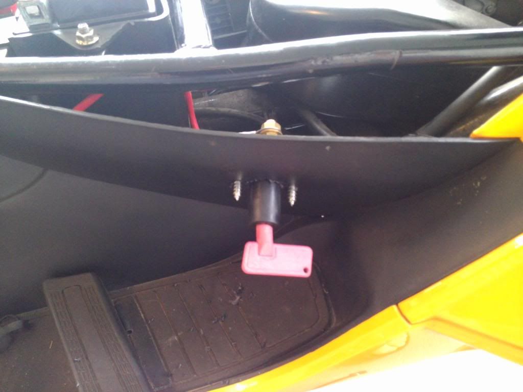
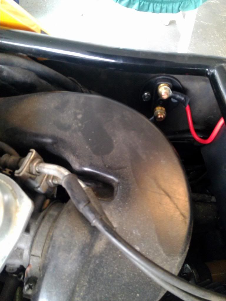
You've helped a lot with your answers and Alley's drawing is correct and he is correct on his description of how to put in a battery disconnect. You always put the disconnect on the positive cable never the negative side. In this case the main positive battery cable goes to the starter relay and also at this point it supplies 12Vdc to the red fused wire to the key ignition. By putting the disconnect in between the battery and the solenoid relay you cut the power off of the entire scooter when the switch is in the off position. If you did wire it like what was drawn in the diagram by the other forum person you mentioned and hit the start button you may have well fried some things in this scooter's circuitry. Now what I would like you to do at this moment where we can do some tests is to simply disconnect the battery disconnect switch you installed and put the positive battery cable back on the starter relay on the side with the "B" on it. Then make sure the cable that goes to the starter is hooked up to the post marked with the "M". Then make sure the negative battery cable is hooked up to the frame. When you confirm all this is correct we'll do some simple tests to see what we need to do to get this scooter back up and running. Now on this comment made by the very person who labeled the starter relay in a picture that IMO led you to wire up this all wrong? I'm sorry about your previous thread, I didn't delete it, it's hidden. Some clown from another forum was trying to use it to drum up business.I don't need to drum up business, have plenty to do and this is a "free" forum not a place to have to try to drum up anything, besides I only made a statement that you had given up and that if you had come elsewhere that we wouldn't have give up trying to help you. At least I'm not posting to put the negative battery cable on the "M" side of the solenoid relay. Let me know when all that is done and I think with just a couple of simple tests we can determine what we need to do to your scooter.  JR |
|
|
|
Post by JR on Jun 26, 2013 5:52:38 GMT -5
Good morning justguy1. I've read all the material and threads about your problem and it seems you have a weird problem for sure. I even put up a thread on my forum hoping you would notice so we could help you there but since you've joined here we'll jump in here and see if we can get you going. www.thescooterprofessor.proboards.com/index.cgi?board=250classchinese&action=display&thread=2764Now I'm going to ask you some questions so I can try to get a better picture of your scooter instead of trying to piece together all the stuff on other threads on other forums and trying to remember it all. First of all is when you got this scooter did it run ok without these issues or did you get it with these troubles? If it was fine when you got it did this happen all of a sudden like going down the road or you just got on one day and found all these problems? I also noticed from previous threads and such that it appears you have installed a battery main disconnect switch to stop the battery draw from the alarm system to keep the battery from discharging when sitting for longer periods of time?    Were you having these problems before or after the switch install and from what terminals did you run this switch too? I would hope that you removed the positive battery cable from the battery, hooked it to the disconnect switch, then ran another wire from the switch to the positive post on the battery? Now I looked at the picture of the plug on your ignition switch and after you answer these questions we'll go from there and I'll ask you to do some tests to see if we can isolate your trouble and go from there. JR |
|
|
|
Post by JR on Jun 24, 2013 21:05:38 GMT -5
I don't see any use in this going on, it's apparent the OP doesn't want or value others opinions right or wrong so we can call it quits and lock it down.
JR
|
|
|
|
Post by JR on Jun 23, 2013 20:49:49 GMT -5
I just edited this where it still makes sense. I'll make this real simple, I thought I had the words used here censored so they wouldn't come up but I spent so much time doing all the abbreviations of the word I missed the correct way to spell it.
This is a forum where you can ask for free advice, suggestions, and opinions. You don't have to agree with the answers and have the right to question anyone's answer.
But in according to the rules here you don't have the right to use profanity. Sometimes people can get a little lets say irritated with each other when discussing a subject and as long as it doesn't get totally out of line tolerance is given up to a point.
But there is zero tolerance for profanity not only by this forums rules but by the software provider Proboards.
I hope you find a solution to your carb problem but keep it clean or go elsewhere if you want to talk like that.
JR
|
|
|
|
Post by JR on Jun 23, 2013 20:21:51 GMT -5
Stepthrutuner, here is the diagram in full PDF. I've got all the diagrams on the Motos and this fellow has asked for help there for some time now and there are several reasons he could have his problems. We'll help him get it fixed now. Also there are two versions of this scooter as far as the diagrams. www.jr-richscooterdoc.com/WD_Cfmoto_Fashion_diagram.pdfJR |
|
|
|
Post by JR on Jun 22, 2013 7:34:38 GMT -5
For those who have converted to 11 pole because of installing EFI the reason was simple, they had either a 6 or 8 pole stator which just ain't gonna cut it on EFI. Also they had to convert to a DC type CDI which is no big deal just extra wiring.
But you're already set up with more amps just because you have a 12 pole stator. IMO I would install the EFI, change every bulb ( except head lights of course) to LED's to squeeze every extra watt out of the system to go to your new EFI and see how she goes? I'm thinking she'll purr right along and as soon as you hook it all up and get her running you can test across the battery terminals at idle and at a higher RPM to see what charging voltage you have.
You'll know at that point how it will do and if it's OK which I believe it will be then money and work saved, if not the money and work is the same now or later. Just my opinion.
JR
|
|
|
|
Post by JR on Jun 21, 2013 18:16:45 GMT -5
Ok even though the diagram is hard to see as far as exact wire colors it's clear enough for me to confirm what I previously said.
In your picture of the wires you have 3 whites on the large plug and a Bl/W and Green/white on the small 2 plug.
3 whites go to R/R which is a 5 pin R/R with black as a ground and red to the battery for charging.
The two plug is blue/white = AC feed to CDI from stator
Green/white = pulse coil from stator to CDI.
The other wires on this CDI which is a 5-wire system are
Black = ground
black/yellow/ = CDI feed to coil
black/red? = engine kill wire which goes through the remote alarm also.
Again hard to read it exactly as far as the color code letters. Do you have a way to scan this diagram and email it to me? If so I could verify the colors possibly with a clearer shot. Also I would to have this diagram for the wiring diagram section I'm working on.
Now IMO the only way a 11 pole stator will charge more than a 12 pole is if the windings on the 11 pole have more winding than the 12 pole ......and the R/R (which is 7 pin) allows for more voltage output than the 5 pin R/R which I doubt?
Also can you look at the bottom of the engine and see if it is this engine a QMI153?
JR
|
|

